TJ (W) L - D5 series synchronous motor digital controllable silicon excitation device
1.Overview
TJ(W)L-D5 Series Full Digital Silicon Controlled Rectifier Excitation Device for Synchronous Motor is the fifth generation of this type developed by XDE in late of 1990s. It is mainly applied for the excitation of synchronous motor (brush or brush less). The core parts of this equipment include Siemens PLC and analog converter. When applied to the excitation adjusting system of synchronous motor, the device can operate in various modes according to different load section. The converter outputs a pulse train for a 3-phase fully controlled rectifier bridge, which may directly trigger the SCR and form the 3-phase full controlled rectifier excitation system. This system has advantages of reliable operation, advanced technology, simple structure, complete function, stable performance, easy commissioning and maintenance etc,.
2.Scope of Application
This rectification device may be applied for the drag motor excitation system used for blowers, pumps, compressors, oxygen generator, ball mill and crusher etc.There is no direct link between the excitation and main circuit of synchronous motor, therefore it is applicable for the synchronous motors at various voltage grade and different capacity.
3.Reference Standard
3.1 GB/T10233-1988 "electrical transmission control equipment Basic test method"
3.2 GB/T12667-1990 "requirements" the basic technology of small and medium synchronous motor excitation system.
3.3 GB/T3797-1989 "second parts: electrical equipment, electrical equipment" with electronic devices:dry type power transformer.
3.4 QB096-98 TJL-D5 type synchronous motor, all digital silicon controlled excitation device, technical specifications,
4 Normal Operating Conditions
4.1 Installed indoors only;
4.2 Installed below 1000 meters above sea level. Derating if over 1000m;
4.3 Relative humidity no more than 85% (20±5℃)
4.4 Ambient temperature no higher than +40℃, no lower than -5℃;
4.5 Installed site must be free from explosive and inflammable gas, conductive dust, and corrosion gas which may deteriorate the insulation performance.
5. Type and Type spectrum
5.1 models:
TJ (W) L-D5/I-U-I: T: synchronous motor; J: brush, W: brushless excitation device; L: D; full digital control; 5: Fifth: I design; excitation forcing ratio (I:1.2, II:1.4); U: rated excitation voltage: I rated excitation current.
Type 5.2 spectrum:
Model | Rated voltage (V) < /strong> | Rated current (safety) | Excitation forcing multiple | Remarks |
TJ(W)L-D5/I-U-I | 50,75,100,125,150,175,200 | 10,20,30,50,100 | 1.2 | Natural air-cooled |
|
| 150,200,250,300,350,400,450,500,600 |
| Forced air-cooled |
TJ(W)L-D5/II-U-I | 50,75,100,125,150,175,200 | 10,20,30,50,100 | 1.4 | Natural air-cooled |
|
| 150,200,250,300,350,400,450,500,600 |
| Forced air-cooled |
6.Selection of excitation transformer and shape of excitation device:
6.1Excitation transformer:
Three phase indoor installation dry-type transformer,380V5%UH,Y/-11;Transformer capacity Sn=U2 I2 10-3[KVA]; U2 =
 [V] Upper limit,I2 =1.15
 IfN[A]
6.2 Shape and Installation Demensions:
Cabinet:
Depth×Width×Height=800×800×2200mm. International standard structure is adopted. Doors lie front and rear, electrostatic spray coating inside and outside. The overall dimensions and weight are determined based on the forms of 3-phase dry rectifier transformer used for ZSSG1-0.6 electrical drive system. When the transformation capacity exceeds 40KVA, it has to be installed outside the cabinet.
7.Control Principe and Instructions
7.1 electrical schematic diagram
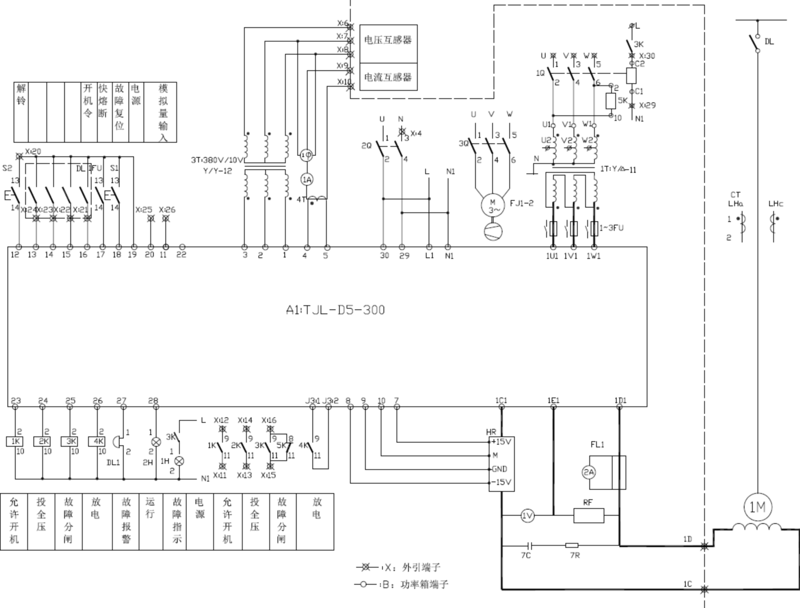
7.2 Composition:
Full Digital Silicon Controlled Rectifier Excitation Device consists of the operational logic control, the excitation adjusting device, excitation transformer, the main loop rectifier bridge, magnetism elimination circuit and feedback module etc. Changing the feedback mode may lead to different adjusting modes of closed loop, such as constant excitation current, constant reactive current adjustment and constant power factor adjustment.
7.3 controller
7.3.1 Main Elements of Model TJL-D5/I-U-300 (Excitation current less than 300A)
The power section comprises a thyristor module SKKT162/16E (160A3) and a discharge module SKKH252/16E (1 250A).
Adjustment section includes: SIEMENS: S7-214-1BD20-0XB0 (224CPU) 1
S7-231-0KD20-0XA0 (Analog input module) 1 blocks
S7-272-0AA20-0YA0(Text display) 1 blocks
Pilot: MC1 (interface board) 1 pieces
MC2(pulse amplification plate) 1 blocks
7.3.2 Main Elements of Model TJL-D5/I-U-500 (Excitation current over 300A):
The data rate includes the thyristor module (500A7) and the diode module (1 500A).
Adjustment section includes: SIEMENS: S7-214-1BD20-0XB0 (224CPU) 1
S7-231-0KD20-0XA0 (analog input module) 1 blocks
S7-272-0AA20-0YA0(text display) 1 blocks
Pilot: MC1 (interface board) 1 pieces
MC2(Pulse amplifier) 1 blocks
7.5 Protection
7.5.1 Main circuit protection
a. Short-circuit protection: Air switch and quick fuse
b. Over excitation protection: The upper limit of the output current of the device is set according to the allowable forcing ratio of the excitation winding of synchronous motor.
c. Undercurrent protection: When the synchronous motor runs under rated conditions, the excitation current will be reduced by 30% of the rated value, in case the synchronous motor might be in an unstable state. In order to prevent underexcitation loss, the underexcitation current shall not be less than 30% of the rated excitation current.
7.5.2 Over voltage protection of excitation circuit:
a. Over voltage of thyristor phase change: protect with R-C.
b. The R-C triangle protection will be applied once the anode voltage of the device's AC incoming line is above 100V
7.5.3 Thyristor rectifier overheating protection: the device will trip if the temperature of radiator exceeds 85℃.
During the asynchronous starting of synchronous motor, the electronic switch of rotor circuit is automatically connected to the starting resistance of 6-10 times the rotor resistance in order to suppress rotor induced overvoltage and improve starting torque.In the starting process of synchronous motor, the device can automatically trip and stop with automatic interlocking when early excitation occurs or motor starts without excitation.The device is provided with the inverter deexcitation and linear resistance deexcitation in case of the expansion of the second damage caused by the short circuit of the stator windings.
7.5.4 The Out-of-step protection is important for synchronous motor and its driven machinery.
The out-of-step state is a complex process of electromagnetic vibration and mechanical vibration, leading to severe damage to the motor and its driven machinery. therefore it is necessary to take all effective measures to prevent such situation. This device, by monitoring the direction and value of power factor and the stator current, could trip immediately in the event of electromagnetic vibration and mechanical vibration.
8.Technical Feature
8.1 The full digit device is designed for the excitation system of synchronous motor, adopting the Siemens PLC and advanced multiple functional transducer module, featuring simple structure, reliable performance and flexible setting
8.2 Standard HMI is adopted, on which running state and relevant data are shown in two lines. 8 function keys and 5 setting keys are responsible for parameter setting, display, system controlling and on-line guidance(in Chinese) etc.
8.3 PLC is adopted, with controllable flexibility and high reliability.
8.4 Flexible main setting method: Slow setting can be done with the motor potentiometer and quick setting with parameters, all through function keys.
8.5 Excitation forcing time can be set up.All settings of the device are continuous digital setting
8.6 The device is equipped with smart error-detection function, monitoring errors occurred in voltage change, phase loss and phase sequence etc. Error-triggered automatic trip is also available.
8.7 Incident logging function keeps the record of the last 100 incidents with exact times, all can be checked on the operation panel.
8.8 Out-of-step protection is employed, functioning trough monitoring the direction and value of the power factor and stator current of synchronous motor.
8.9 Re-synchronizing of out-of-step logic: After detecting the out-of-step, re-excitation starts according to logic modes and steps.
8.10 This excitation device has function of no load testing, automatically identifying no-load state and normally starting without any additional setting.
8.11 This device has automatic deexcitation function
8.12 Over-excitation protection setting: 0-200% rated excitation current.Under-excitation protection setting: 0-100% rated excitation current
8.13 Automatic excitation forcing: Automatic detection of grid voltage. When it is lower than forced excitation point, excitation forcing begins automatically. Trip will be caused if excitation forcing is conducted at low voltage for long period.
8.14 Control mode: a) Constant excitation current adjustment, b) Constant power factor adjustment of active compensation, c) Closed loop adjustment of constant power factor, e) constant reactive adjustment.
8.15 System display: a) Excitation current display, b) Excitation voltage display, c) Motor side voltage display, d) Stator current display, e) Active display, f) Power factor display, g) Working state display.
8.16Text display is provided with Chinese menu: Operation HMI is suitable for Chinese. each operation is guided with Chinese instruction, making it easy to parameter setting, trouble shooting and help to shorten the maintenance time.
8.17 Running parameter is stored in the EEPROM.
9.Performance Feature
9.1 The device ensures long - term continuous operation at 110% of the rated output current.
9.2 Exciting towards polarity allows 5% of slip frequency (exciting towards polarity means the excitation 9.3 current and the induction current of the excitation winding remain same direction). The device is also equipped with the backup excitation(time excitation). When excitation fails, the motor stops automatically and shown on display.
9.4 Constant power factor adjusting excitation system, the load of synchronous motor varies from none to rated limit, while power factor maintains basically constant.
9.5 When the voltage of the power grid drops symmetrically to 80% of the rated value, the device can automatically provide excitation current with forcing ratio of 1.2-1.5 times of the rated current.
9.6 The excitation forcing time can be selected from 10 seconds to 50 seconds, or it can be set according to the current temperature of the excitation winding of synchronous motor.
9.7 When out-of-step situation occurs. the device could identify the direction of power factor and the value of stator current.
9,8 The device will conduct the automatic deexcitation, when the synchronous motor starts and stops.
10 Ordering Instruction
The Customer shall provide the following information when ordering the Full Digital Silicon Controlled Rectifier Excitation Device for Synchronous Motor.
Model, specification and number of sets of Full Digital Silicon Controlled Rectifier Excitation Device for Synchronous Motor.
Example of product model:Synchronous motors start at constant current excitation with full or reduced voltage, rated output voltage 75V, rated output current 200A, excitation forcing ratio 1.4 times, model number TJL-D5/II-75-200, 3 units
The customer shall provide the relevant parameters of synchronous motor in order to optimize the settings before delivery.
a. Model of synchronous motor;
b. Capacity;
c. Starting time;
d. Rated excitation voltage;
e. Rated voltage of the stator
f. Rated current of the stator
g. Transformation ratio of the current transformer of the stator
h. Rated excitation current;
i. Resistance value when excitation winding at 75℃.
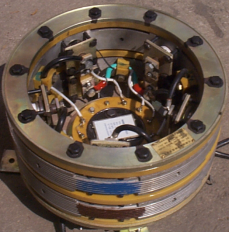
XZL-P44(5)-2 Synchronous Motor Brush-less Excitation Rotating Rectifier
1.Introduction
The XZL-P44-2 series products are the rotary rectifier equipments used in the general synchronous motor brushless excitation systems. The XZL-P45-2 series products are special rotary rectifiers for increased-safety synchronous motor with brushless excitation. As core of the brushless excitation system, this equipment is fifth generation product developed in the late of 1990s by XDE. It features simple structure, advanced technology, reliable operation, stable performance, small size, light weight, easy installation, simple commissioning and free of maintenance. Besides, by complete set supplying, it may reduce the workload for motor supplier in terms of rotatory rectifier designing, machining and assembling.
2 scope of application
Applied for synchronous motor with brushless excitation system (including increased-safety type).
Applible for synchronous motor with brushless excitation system under the condition that rated rotation speed is 1500r/min or below.
3 Reference Standard
GB3836.1-2000《Electrical equipment for explosive gas atmospheres - part first: General requirements》 ;
GB3836.3-2000《Electrical equipment for explosive gas atmospheres - Part third: increased safety type“e” 》 ;
JB8973-1999《Technical specification for increasing safety type brushless excitation synchronous motor》 ;
QB161-2002《XZL-P45-2 series products — increased safety synchronous motor; brushless excitation rectifier device; technical specifications》 ;
JB8974-1999《Technical specifications of TAW series increased safety brushless synchronous motor》。
QB113-2000《Technical specification for brushless excitation rotating rectification device of XZL-P44-2 series synchronous motor》 ;
4 Operational Conditions
Installed below 1000 meters above sea level. Derating if over 1000m;
Running temperature no higher than +40℃, no lower than -5℃; heating temperature of the rectifier no higher than +80k
Running under IP54 protection cover
5 rotary rectifier type
Type:
XZL (rotating rectifier);
P (flat type rectifier);
4 (rotary rectifier diameter: 420mm;
) 4 (general);
2 (rated speed is 1500r/min and below any speed).
Type: XZL-P45-2
XZL (rotating rectifier);
P (flat type rectifier);
4 (rotary rectifier diameter: 420mm;
) 5 (increasesafety);
2 (rated speed is 1500r/min and below any speed).
6tbasic parameters of rotary rectifier
6.1 schematic wiring diagram;

Principle diagram (as shown in the figure)
Output current, 300A
Output voltage, 200V
Rotary rectifier, 500A/2000V
Max. outer diameter of rotary rectifier: 420mm
Rated rotation speed 1500r/min or below
Weight of rotary rectifier: approx. 60kg